12v 30a Relay Wiring Diagram Ground Output
Weak negative output to strong ground output. So this two small screw terminals on the side of the generator are for ground.
Wiring Loom Harness Kit 12V Relay Red Rocker Switch 30A Fuse For LED Light Bar eBay

12 volt relay wiring schematic.

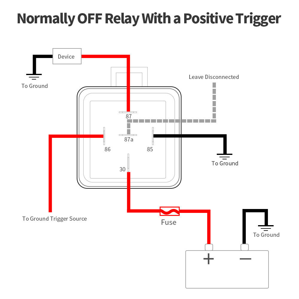
12v 30a relay wiring diagram ground output. In your case, just use the positive output to your factory horn to the trigger pin of your relay (pin 86). Weak negative output to strong ground output relay wiring diagram. The real benefit behind a relay is more than automation.
Car qook automotive dc 12v 12 volt 30a amp spdt wiring power relay. Grounding the switch will create a positive 12 volt output at pin relays are used to send full power to a particular device while allowing a switch for. Often it is necessary to provide a stronger ground than the negative output of an alarm or keyless entry can provide.
Variety of 12 volt solenoid wiring diagram. Here is a video on how you can test a relay with or without a diagram. The purpose of a relay is to automate this power to switch electrical circuits on and off at particular times.
Bosch relay 12v 30a wiring diagram amalgamagency.co. Positive trip from switch from alarm door driver output to door locks, power (12v positive) and ground 87 86 12v positive 87a 30 85 87 87a 85 factory lock relay system this. If the contact is broken with the relay at rest then the relay is referred to as normally open (no).
12v 40a relay 4 pin wiring diagram. Switch wiring diagram before wiring switch positive out + positive in + t h e c o m s t e r e o www.utvcom.com www.utvcom.com relay 40/30a 12v dc thecom or other accessory note: The iso mini relay we have looked at above has 4 pins (or terminals) on the body and is referred to as a make & break relay because there is one high current circuit and a contact that is either open or closed depending upon whether the relay is at rest or energised.
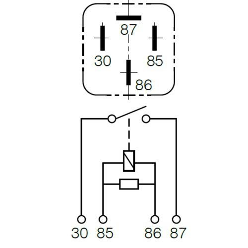
31 battery negative terminal, or ground, direct 49, x turn signal flasher input 49a, l turn signal flasher output 4 pin high capacity normally open mini relays 85 stock code description type protection wiring diagram 6646b p141270x 12v, 70a diac 1 form a (30/87=9.5mm (american) 87 30 86 30 86 85 87 5 pin changeover mini relays Wiring diagrams for trucks are contained in a separate wiring. The relay features a plastic housing with mounting tab for easy installation.
When this is the case, use the following diagram. If you need a relay diagram that is not included in the 76 relay wiring diagrams shown below, please search our forums or post a. A normally open relay will switch power on for a circuit when the coil is activated.
12v relay wiring diagram 5 pin relay fuse box diagram. This is a device consisting of a coil of wire wrapped around an iron core. A normally closed relay will switch power off for a circuit when the coil is activated.
If you want a normally open relay, you will wire to 87. 5v relay pin diagram click the image to enlarge it relay pin configuration. In this diagram, our switch is connected on the ground or negative side.
Preset pressure for fan relay ground page 2 electric fan relay wiring optional fan temp switch sending unit (self grounding or separate ground terminal type) pink red black orange relay trigger to a fused 12 v ignition source 12 volt battery source. This diagram was designed for 12 volt systems but can also be used for 6 volt systems. Although most relays are labeled on the bottom, for easy identification to the power source, you can always find the 30 pin set center and perpendicular to the output pins.
Connecting additional devices to the remote turn. Power (12v positive) and ground 87 86 12v positive 87a 30 85 87 86 87a 30 factory lock relay system this wiring diagram is for cars with factory lock relays. Spd speed input required only if using lock on speed setting, leave unconnected otherwise.
This post goes to 12v at the same time the output (starter side) of the relay does. Posted by anonymous on apr 01, want answer 0. Free download with regard to 12v 30 amp relay wiring diagram by admin from the thousand pictures on the web about 12v 30 amp relay wiring diagram we selects the.
Nlr need a wiring diagram for a nlr 12v 30a relay. Dozens of the most popular 12v relay wiring diagrams created for our site and members all in one place. On how you need the switch to work.
Relay 4 pin 12v 30a open contact. The following diagrams show some common relay wiring schemes that use 4 pin iso mini relays. Connect this wire to the red wire of the siren and the black wire of the siren to chassis ground, preferably at the same point you connect the main modules ground wire.
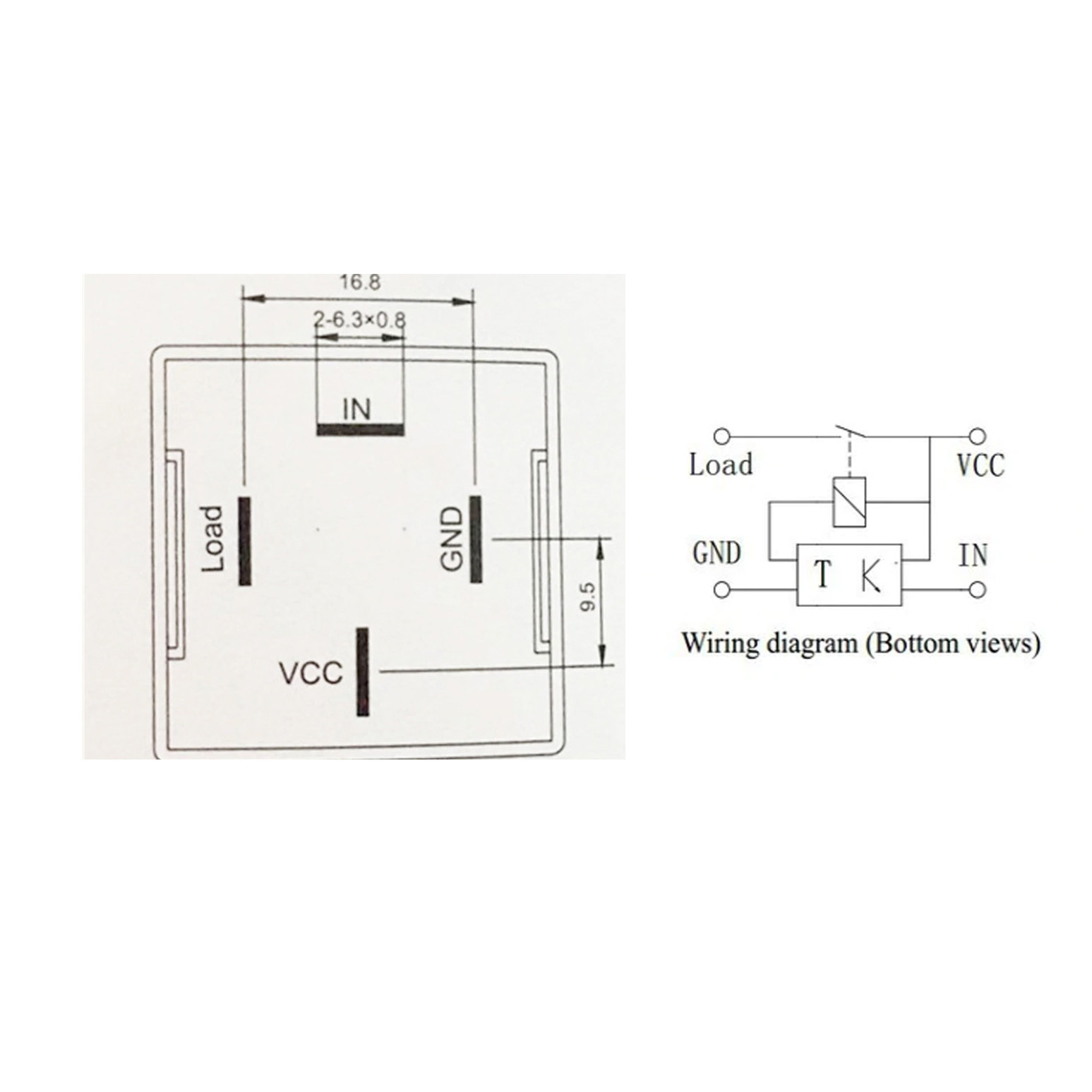
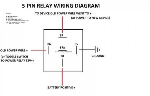
Wiring diagram terminal 86 12v trigger terminal 85 ground trigger terminal 30 12v source terminal 87 connects to device terminal 87a. Manual fan on override switch pink orange red black black. 5 pin relay 5 pin relays provide 2 pins (85 & 86) to control the coil and 3 pins (30,.
September 23, 2021 on basic relay wiring diagram. If you want a closed relay, you will want to wire to 87a. Brown (+) siren output this wire supplies a (+) output for the siren.
Nissan pickup need wiring plan. · 87 = high powered output load or power to accessory + · 86 = relay trigger wire (acc or. Pin 30 will be the positive to your new air horn (negative from the horn goes to ground), ground pin 85, and run your 12 gauge wire from the battery to pin 87.
Clicking this will make more experts see the question and we will remind you when it gets answered. So a single pole double throw has a mutual. With this kind of an illustrative guidebook, you are going to have the ability to troubleshoot, avoid, and full your tasks easily.
Wiring diagram for a 4 pin relay wiring diagram is a simplified agreeable pictorial representation of an electrical circuitit shows the components of the circuit as simplified shapes and the capacity and signal connections with the devices. Bosch type relay wiring diagrams. For 2 wire pulse generators connect one wire to ground and the other wire to spd terminal.
By vallery masson updated on september 23, 2021.
Bosch Relay 12V 30A Wiring Diagram Database

1 Channel 30A Relay Module Optocoupler Isolation 12V High/Low Level Trigger RS1825 REES52

12V 30A Normally Open 4 Pin Reverse Pin Relay w/ Resistor Protection Blister Pack Nold
Automotive 30a 12v Timer Delay Relay Mr Positive NZ
12V 30A Relay 5 Pin Wiring Diagram Database

China 12v 30a/40a 5pins Relay With Resistance Manufacturers and Suppliers Factory Wholesale

Bosch Relay 12V 30A Wiring Diagram Wiring Diagram And Schematic Diagram Images

The "you already have a relay box" Relay Box NAXJA Forums North American XJ Association
remote hot start set up? how do I??? Auto Electrics OzFalcon Ford Falcon Owners Club

MICTUNING IP67 Relay Harness Set 12V 5PIN SPDT Bosch Relay+WIRING 5 PACK30/40A eBay
6pcs Car 5PIN SPST Relay Switch Harness 12V 30A Wire Set With 30 AMP Fuse Holder eBay

Wiring Diagram For A12volt 30 Amp. Relay

30 Amp Relay Wiring Diagram Bosch Relay 12v 30a Wiring Diagram Amalgamagency Co Circuit
25 Pack 40/30 AMP 5 Pin SPDT 12 V DC Bosch Style Relay Switch for Electrical Automotive Truck

Bosch Relay 12V 30A Wiring Diagram Database

12v 30a Relay Wiring Diagram
53 12 Volt Relay Diagram Wiring Diagram Plan

6pcs Car 5PIN SPST Relay Switch Harness 12V 30A Wire Set With 30 AMP Fuse Holder eBay

12v Automotive Relay Bank & Socket Harness MGI SpeedWare