Fan Motor Wiring Diagram Single Phase
The first component is symbol that indicate electrical element in the circuit. A wiring diagram is a simplified traditional pictorial representation of an electrical circuit.
3 wire and 4 wire Condensing Fan Motor Connection HVAC

The other thing that you will get a circuit diagram would be traces.

Fan motor wiring diagram single phase. Fan motor wiring diagram single phase. Terminal markings and internal wiring diagrams single phase and polyphase motors meeting nema standards b. Wiring a motor for 230 volts is the same as wiring for 220 or 240 volts.
The basic diagram (view a) shows a circle with two leads labeled t1 and t2. 0 75hp 110 220 single phase motor circuit diagram electrical diagram electrical circuit diagram. Baldor motor wiring diagram single phase wiring diagram is a simplified within acceptable limits pictorial representation of an electrical circuit it shows the components of the circuit as simplified shapes and the knack and signal connections in the company of the devices.
Baldor single phase 230v motor wiring diagram. L1 and l2 are designated as the two connection points representing the two electricity flow path inherent with single phase circuits where a single phase supply voltage is fed to the motors internal circuit. Residential power is usually in the form of 110 to 120 volts or 220 to 240 volts.
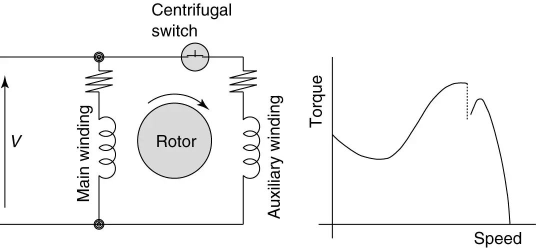
Otherwise, the structure won’t function as it should be. Angelo on june 23, 2021. The split phase motor can be found in applications requiring 1/20 hp up to 1/3 hp, meaning it can turn anything from blades on a ceiling fan, washing machines tubs, blower motors for oil furnaces, and small pumps.
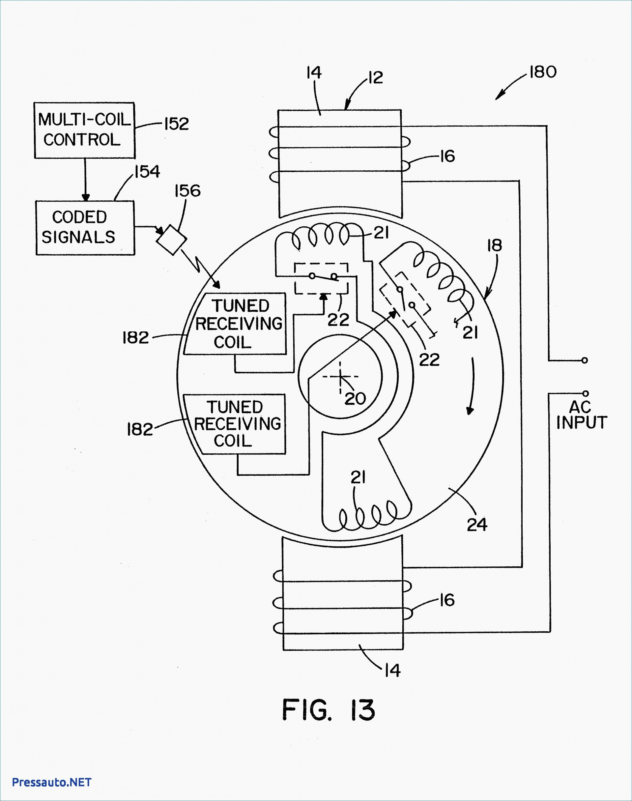
All circuits usually are the same voltage ground single. Types of single phase induction motors electrical a2z single phase induction motors are traditionally used in residential applications such as ceiling fans air conditioners washing machines and refrigerators single phase motor wiring with contactor diagram the plete guide of single phase motor wiring with circuit breaker and contactor diagram has 803 x 1213. In this video, jamie shows you how to read a wiring diagram and the basics of hooking up an electric air compressor motor.
Data on the motor for wiring diagrams on standard frame ex e, ex d etc. It usually shows how to wire the motor for common configurations such as 110 to 125 volts or 220 to 250 volts and occasionally 208 volts. Ceiling fan wiring diagram with capacitor connection this is a simple illustrated circuit diagram of ceiling fan to be noted that the wiring diagram is for ac 220v single phase line with single phase.
Diagram dd5 two speed motors for all other single phase wiring diagrams refer to the manufacturers data on the motor. Split phase motor wiring diagram. Click here to view a capacitor start motor circuit diagram for starting a single phase motor.
These tips can be used on most ele. Fan wiring diagram 3 phase motor. It has a 3 speed fan motor.
Diagram dd6 diagram dd7 m 1~ ln e diagram dd8 ln e l1 l2 l3 s/c z1 u2 z2 u1 cap. Proper ceiling fan connection with regulator switch and capacitor etechnog home electrical wiring ceiling fan wiring ceiling fan switch. These instructions will probably be easy to comprehend and implement.
Learn how a capacitor start induction run motor is capable of producing twice as much torque of a split. Single phase 3 speed fan motor wiring diagram. Wiring diagram will come with numerous easy to follow wiring diagram directions.
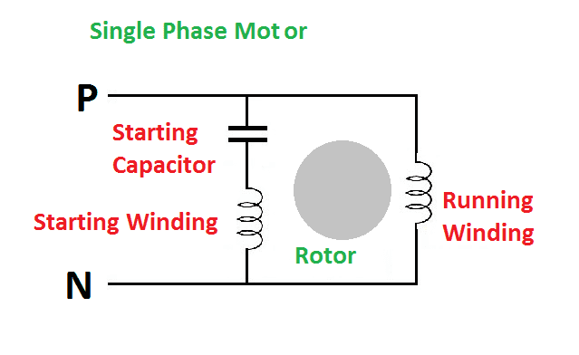
There are two things which are going to be present in any single phase motor wiring diagram with capacitor. 220v single phase motor wiring diagram. There are a number of different construction methods used, but the basic principle is the same.
It is intended to help all the typical user in building a correct program. A circuit is usually composed by many components. Single phase motor wiring diagram with capacitor start capacitor run.
Firstly, the stator winding is connected in star an. Each part should be set and linked to other parts in particular way. Diagram dd6 diagram dd8 m 1~ ln e diagram dd9 m 1~ ln e white brown blue l1 l2 n s/c bridge l1 and l2 if speed controller (s/c) is not required diagram dd7 ln e l1 l2 n s/c z2 u2 z1 u1 cap.
Dd 1, 2, 3 o*ap/apv. This procedure works for electric motors that are able to operate with either 110 or 220 volt power by changing a few electric motor electricity diy electrical Please note that some of these documents were originally produced a long time ago and have now been converted to pdf format for easy access online.
Capacitor Electric Motor Wiring Diagram Single Phase
ac How to wire 1phase 3speed motor Electrical

Wiring Diagram For 220 Volt Single Phase Motor, http
Electric Fan Motor Winding Diagram
Capacitor Start Motor Wiring Diagram Pdf

Single phase Motor Wiring And Controlling Using Circuit

Dayton Electric Motors Wiring Diagram Download Cadician
Wiring Diagram For 220 Volt Single Phase Motor

Wiring Diagram Panel Electric 1 Phase

1 Phase Fan Motor Wiring Diagram Wiring View And
3 Phase To Single Phase Wiring Diagram
Dayton Hoist Wiring Diagram Gallery

3 wire submersible well wiring diagram get free Circuit

Smith and Jones Electric Motors Wiring Diagram Download

120 Volt Capacitor Start Motor Wiring Diagram frydisblog
1 Phase Fan Motor Wiring Diagram Wiring View And
Types of Single Phase Induction Motors Single Phase
Single Phase Motor Wiring Diagram With Capacitor Start

Electric Fan Wiring Diagram Philippines Dowell