L1 L2 Wiring Diagram
Ac drives, ac power must be connected to terminals l1 and l2. Wiring 220 volt electrical outlet
Electrical Wiring L1 L2 Home Wiring Diagram
More about 220volt electrical wiring.

L1 l2 wiring diagram. L1 and l2, for example, imply that the motor voltage may be 240 volts. Power supply symbols 1 2 a b figure 5. Diagram dd9 1ø wiring diagrams ln e l1 l2 l3 s/c z2 u2 z1 u1 cap.
New pump's diagram suggests line on l1 (note: This connection is used for fault current only. I think the most important thing is consistency.
Is there a wiring diagram for a 240 volt contactor? Air conditioner 230v l1 vs l2 wiring diagram. Light switch wiring diagram l1 l2.
If all 3 elements were identical, there wont be any neutral current to switch, and the neutral only carries the imbalance. L1 l2 com wiring diagram wiring diagram is a simplified suitable pictorial representation of an electrical circuit. When l1 is on l2 would be off.
Discussion in 'electrics uk' started by dimwit1960, 11 sep 2016. L1 and l2 indicate that the motor voltage may be 240 volts. Together, they show the motor voltage.
T1 t2 t3 t4 t5 motor lead wires. The t symbol designation refers to the terminal or termination, which in this case is a wire lead that. If white is used in a house as l1, then it.
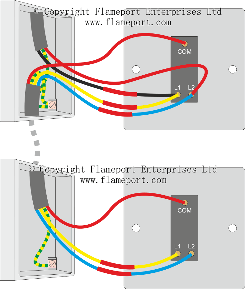
The yellow wire goes in the common terminal, red in the l1 terminal and blue goes in the l2 terminal. L1 (line 1) is a red wire and l2 (line 2) is a black wire. They will be marked so you can tell which is.
Print the wiring diagram off plus use highlighters to trace the signal. Wiring connections to l1, l2, l3 and pe terminal blocks the pe designates the termination for the protective earth or in our usa terminology the ground. The l symbol designation refers to the line, or the incoming circuit wires that provide the power for the motor.
The grey wire goes in the common terminal, brown in the l1 terminal and black goes in the l2 terminal. What each of the wires is for, how it works! L1 l2 com wiring diagram wiring diagram is a simplified suitable pictorial representation of an electrical circuit.
Our virtual experts can diagnose your issue (for free!) and resolve simple problems. Dimmer switch wiring diagram l1 l2 from www.lightwiring.co.uk. Also you should know that the main lines are marked l1, l2 and n.
Wiring diagrams for l1 and l2 motors the l symbol denotes the line, or the incoming circuit wires that supply electricity to the motor. When l1 is off l2 would be on. When you make use of your finger or perhaps the actual circuit with your eyes, it is easy to mistrace the circuit.
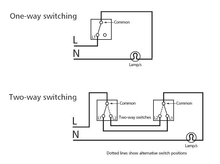
Light wiring diagram if you need to know how to fix or modify a lighting circuit, you’re in the right place…. L1 and l2 indicate that the motor voltage may be 240 volts. Two way switching allows you to control a light from two locations.
T1 t2 t3 t4 t5 t6 t7 t8 t9 t10 t11 t12 t13 t lead wires for motors and fans these are the terminal leads of the motor or fan. What are the l1 and l2 on a wiring diagram? L1 and l2 motor wiring the l symbol designation refers to the line, or the incoming circuit wires that provide the power for the motor.
The other ends are called the line end (denoted as ‘l1’, ‘l2’ and ‘l3’). L1 l2 com wiring diagram. Wiring diagrams for l1 and l2 motors the l symbol denotes the line, or the incoming circuit wires that supply electricity to the motor.
Legend plug 2 1 schematic diagram 1. The 3 phases l1 l2 and l3 would be coloured brown black and grey. The text neutral line confuses me).
The three winding end connected together at the centre are is called the neutral (denoted as ‘n’). L1 and l2 motor wiring. 1 trick that we 2 to printing a similar wiring plan off twice.
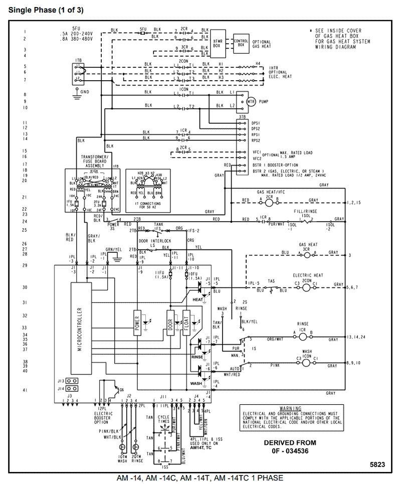
1.75 blk htr1 dd1 or cbdisc 6 8 blk 4 2 l1 l1 l2 l2 dd1 fig. The voltage between two lines (for example ‘l1’ and ‘l2’) is called the line to line (or phase to phase) voltage. Having both an l1 and l2 indicate that the motor voltage may be 240 volts.
However, only one of these lines (l1 in this case) will have power attached to it at any given time. What colours are l1 l2 l3? I understand that it really doesn't make a difference, as long as my line (in) is the side that is switched (which is is), so the motor.
It shows the components of the circuit as simplified shapes and the capability and signal links along with the devices. I have tried wiring in the two commons then wiring switch one l1 connection and switch 2s l2 connection then bridging the l2 on switch one and l1 on switch two, i can get the two switches to work this way but only if the partner switch to the 2 way light is left on. 2 way switch 3 wire.
I'm wiring a new pump (usq1072) for 115v operation the old pump's diagram (115v) has line on l2. L1 and l2, for example, imply that the motor voltage may be 240 volts. Wiring (use copper conductors only) figure 3.
The l1 is the switched live going out to the lightthey will be marked so you can tell which is which. Connect now shop homex recommended products
L1 L2 Com Wiring

Light Switch Wiring Diagram L1 L2 yazminahmed

Wiring Double Light Switch L1 L2 L3 Cleaver Single Pole Contactor 240V Wiring Diagram Trusted

Dimmer Switch Wiring Diagram L1 L2
13 Nice Wiring Double Light Switch L1 L2 L3 Collections Tone Tastic

Wiring A Switch L1 L2 New 4, Switch Wiring Diagram Multiple Lights, Four, Switch Wiring Diagram

Light Switch Wiring L1 L2 Common
Dimmer Switch Wiring Diagram L1 L2 Database Wiring Diagram Sample
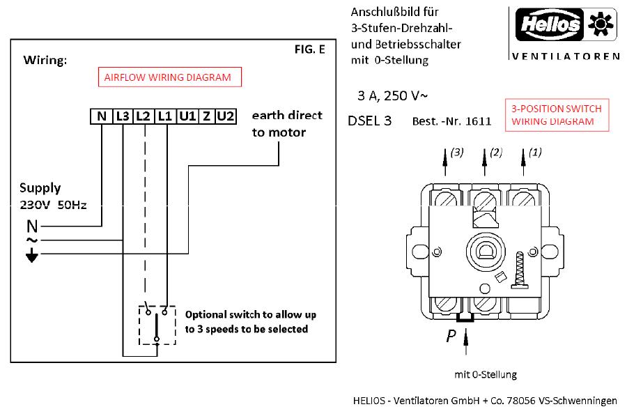
Ask The Trades 3 Position Switch wiring problem
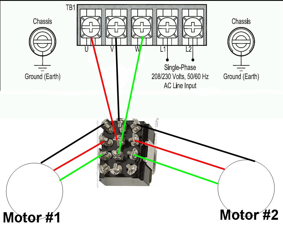
1 vfd 2 motors
Wiring A Switch L1 L2 New Three, Light Switching, Intermediate Switch Collections Tone Tastic

Light Switch Wiring L1 L2 Common
Wiring A Switch L1 L2 Brilliant Wiring Diagram L1 L2, Electrical Wiring Gfci Outlet, Switch

Light Switch Wiring Neutral Wire Practical Light Switch Wiring Diagram L1 L2 Inspirational, To

Light Switch Wiring Diagram L1 L2 yazminahmed

Light Switch Wiring L1 L2 Common

Dimmer Switch Wiring Diagram L1 L2 Database Wiring Diagram Sample

Wiring Double Light Switch L1 L2 L3 New Wiring Diagram L1 L2 Fresh Receptacle Wiring Graphic

Dimmer Switch Wiring Diagram L1 L2 Wiring Diagram
